Site sections
Editor's Choice:
- Business with China - where to start, how to find suppliers + TOP-15 goods from China and a list of trading platforms
- Where to invest 1000 dollars
- Three common misconceptions and six life tips
- How can maternity capital be used - what needs can be spent on maternity capital
- Caramel apples - a new idea for business
- Ready business plan for beginners
- Gypsum tiles for stone: 7 advantages of the material
- How to buy the best and interesting unusual goods from China for home, gifts and sale on Aliexpress in Russian?
- Business plan for opening a bath
- Where to spend maternity capital before the child is 3 years old
Advertising
| 3. Power and energy measurement |
|
Currently, it is necessary to measure the power and energy of direct current, active power and energy of alternating single-phase and three-phase current, reactive power and energy of three-phase alternating current, instantaneous power value, as well as the amount of electricity within a very wide range. Electric power is determined by the work done by the source of the electromagnetic field per unit of time. Active (absorbed by the electric circuit) power P a = UIcos > = I 2 R = U 2 / R,(1) where U, I - effective values of voltage and current; - phase shift angle. Reactive power R R = UIsin = I 2 X. (2) Full power P n = UI= PZ. These three types of power are related by the expression P= (P a 2 + P 2 R ) (3) So, the power is measured within 1 W ... 10 GW (in DC and single-phase alternating current circuits) with an error of ± (0.01 ... 0.1)%, and at microwave frequency - with an error of ± (1 ... 5) %. Reactive power from units var to MVar is measured with an error of ± (0.1 ... 0.5)%. The measurement range of electrical energy is determined by the measurement ranges of rated currents (1 nA ... 1O kA) and voltages (1 μV ... 1 MB), the measurement error is ± (0.1 ... 2.5)%. Reactive energy measurement is of interest only for industrial three-phase circuits. Power measurement in DC circuits. When indirectly measuring power, the ammeter and voltmeter method and the compensation method are used. Ammeter and voltmeter method. In this case, the devices are switched on according to two schemes (Fig. 1). The method is simple, reliable, economical, but has a number of significant disadvantages: the need to take readings for two
Rice. .one. Circuits for measuring power according to the readings of a voltmeter and ammeter for small (a) and large (b) load resistances devices; the need to make calculations; low accuracy due to the summation of the error of the devices. Power R X , calculated from the readings of the instruments (Fig.1a), has the form It is greater than the actual value of the power consumed in the load P n by the value of the power consumption of the voltmeter R v , i.e. P n = R X - R v . The error in determining the power in the load is the less, the greater the input resistance of the voltmeter and the lower the load resistance. Power R X , calculated according to the readings of the devices (Fig. 1, b), we have the form It is greater than the actual value of the power consumption of the load by the value of the power consumption of the ammeter R A . The methodical error is the less, the lower the input resistance of the ammeter and the higher the load resistance. Compensation method. This method is used when a high accuracy of power measurement is required. The compensator measures the load current and the voltage drop across the load. The measured power is determined by the formula P= U n I n . (4) In direct measurement, active power is measured by electromechanical (electrodynamic and ferrodynamic systems), digital and electronic wattmeters. Electrodynamic wattmeters are used as portable devices for accurate power measurements (class 0.1 ... 2.5) in DC and AC circuits with a frequency of up to several thousand hertz. Ferrodynamic panel voltmeters are used in AC circuits of industrial frequency (class 1.5 ... 2.5).
In a wide frequency range, digital wattmeters are used, the basis make up various power converters (for example, thermoelectric), DCT, microprocessor and central control center. In digital wattmeters, automatic selection of measurement limits, self-calibration and an external interface are provided. To measure power in high-frequency circuits, special and electronic wattmeters are also used. Reactive power meters (varmeters) are used to measure reactive power at low frequencies, in which, by using special circuits, the deviation of the moving part of the electrodynamic MI is proportional to the reactive power. The inclusion of electromechanical wattmeters directly into the electrical circuit is permissible at load currents not exceeding 10 ... 20 A, and voltages up to 600 V. Power measurement at high load currents and in high voltage circuits is performed by a wattmeter with measuring current transformers TA and voltage TV(fig..2). Measurement of active power in three-phase current circuits. Method of one wattmeter. This method is used only in a symmetrical system with a uniform phase load, the same phase angles between the vectors I and U and with full voltage symmetry (fig..3).
Fig. 3. Schemes for connecting a wattmeter to a three-phase three-wire circuit with full symmetry of the load connection: a- a star; b - triangle; in ~ - with artificial zero point
Fig. 4. Schemes for connecting two wattmeters in a three-phase circuit: a- in the 1st and 3rd; b- in the 1st and 2nd; v- in the 2nd and 3rd In fig. .3, a the load is star-connected and the zero point is available. In Fig. 3, b the load is delta connected, the wattmeter is in phase. In fig. .3, v the load is delta connected to an artificial zero point. An artificial zero point is created using two resistors, each of which is equal to the resistance of the voltage winding circuit of the wattmeter (usually indicated in the data sheet for the wattmeter). The readings of the wattmeter will correspond to the power of one phase, and the power of the entire three-phase network in all three cases of switching on the device will be equal to the power of one phase multiplied by three: P =3 P w Method of two wattmeters. This method is used in a three-phase three-wire circuit, regardless of the connection scheme and the nature of the load, both with symmetry and with asymmetry of currents and voltages. Asymmetry is a system in which the powers of the individual phases are different. The current windings of the wattmeters are connected to any two phases, and the voltage windings are connected to line voltages (Fig. 4). The apparent power can be expressed as the sum of the readings of the two wattmeters. So, for the circuit shown in Fig. 4, a, where 1 is the phase angle between the current I 1 and line voltage U 12, 2 - phase angle between current I 3 and line voltage U 32 . In a particular case, with a symmetric voltage system and the same phase load 1, = 30 ° - and 2 = 30 ° - , the readings of the wattmeters will be: With an active load ( = 0), the readings of the wattmeters will be the same, since P W ] = P W 2 IUcos30 °. With a load with a shear angle cp = 60 °, the readings of the second wattmeter are zero, since P W 2 = IU cos (30 ° + ) = IU cos (30 ° + 60 °) = 0, in which case the power of the three-phase circuit is measured with one wattmeter. With a load with a shift angle > 60 °, the power measured by the second wattmeter will be negative, since (30 ° + ) is greater than 90 °. In this case, the moving part of the wattmeters will turn in the opposite direction. For counting, it is necessary to change the phase of the current in one of the wattmeter circuits by 180 °. In this case, the power of the three-phase current circuit is equal to the difference between the readings of the wattmeters The three wattmeter method. To measure the power of a three-phase circuit with an unbalanced load, three wattmeters are switched on, and the total power in the presence of a neutral wire will be equal to the arithmetic sum of the readings of three wattmeters. In this case, each wattmeter measures the power of one phase, the readings of the wattmeter, regardless of the nature of the load, will be positive (the parallel winding is switched on to the phase voltage, that is, between the linear wire and the neutral wire). If the zero point is not available and there is no zero wire, then parallel circuits of devices can form an artificial zero point, provided that the resistances of these circuits are equal to each other. Measurement of reactive power in single-phase and three-phase circuits. Despite the fact that reactive power does not determine either the work performed or the energy transmitted per unit of time, its measurement is also important. The presence of reactive power leads to additional losses of electrical energy in transmission lines, transformers and generators. Reactive power is measured in reactive volt-amperes (var) both in single-phase and in three-phase three- and four-wire alternating current circuits by electrodynamic and ferrodynamic or wattmeters specially designed for measuring reactive power. The difference between a reactive wattmeter and a conventional one is that it has a complicated parallel circuit to obtain a phase shift of 90 ° between the vectors of current and voltage of this circuit. Then the deviation of the moving part will be proportional to the reactive power R R = UIsin . Reactive wattmeters are mainly used for laboratory measurements and verification of reactive meters. The reactive power in a three-phase symmetrical circuit can also be measured with an active wattmeter: for this, the current coil is connected in series to phase A, the voltage coil between phases B and C. Power measurement in high frequency circuits. For this purpose, both direct and indirect measurements can be used, and in some cases, indirect measurements may be preferable, since sometimes it is easier to measure the current and voltage across the load than directly power. Direct measurement of power in high and high frequency circuits is performed by thermoelectric, electronic wattmeters, Hall effect-based wattmeters, and digital wattmeters. Indirect measurements are carried out using an oscilloscope method. It is mainly used when the circuit is powered by a non-sinusoidal voltage, at high frequencies, low-power voltage sources, etc. Energy measurement in single-phase and three-phase circuits. Energy is measured by electromechanical and electronic electricity meters. Electronic meters of electrical energy have better metrological characteristics, greater reliability and are promising instruments for measuring electrical energy. 4. Measurement of phase and frequency The phase characterizes the state of the harmonic signal at a certain point in time t. Phase angle at the initial moment of time (origin), i.e. at t = 0, are called zero(initial) phase shift. The phase difference is usually measured between current and voltage or between two voltages. In the first case, they are more often interested not in the phase angle itself, but in the value of cos or power factor. Cos is the cosine of the angle by which the load current leads or lags behind the voltage applied to this load. Phase Shift two harmonic signals of the same frequency are called the modulus of the difference between their initial phases = | 1 - 2 |. The phase shift does not depend on time if the initial phases 1 and 2 remain unchanged. The phase difference is expressed in radians or degrees. Phase angle measurement methods. These methods depend on the frequency range, signal level and shape, on the required accuracy and the availability of measuring instruments. Distinguish between indirect and direct changes in the phase angle. Indirect measurement. This measurement of the phase angle Between the voltage U and current I in load in single-phase circuits carried out using three devices - a voltmeter, an ammeter and a wattmeter (Fig. 5). The angle is determined by calculation from the found value of cos:
The method is usually used at industrial frequency and provides low accuracy due to the methodical error caused by the devices' own consumption, it is quite simple, reliable, and economical. In a three-phase symmetrical circuit, the cos value can be determined by the following measurements: power, current and voltage of one phase; measurement of active power by the method of two wattmeters; measurement of reactive power by the method of two wattmeters with an artificial neutral point. Among the oscillographic methods for measuring the phase, the methods of linear sweep and ellipse are most widely used. The oscillographic method, which makes it possible to observe and record the signal under investigation at any time, is used in a wide frequency range in low-power circuits with rough measurements (5 ... 10%). The linear sweep method involves the use of a two-beam oscilloscope, on the horizontal plates of which a linear sweeping voltage is applied, and on the vertical plates - the voltage, between which the phase shift is measured. For sinusoidal curves on the screen, we get an image of two voltages (Fig. 6, a) and according to the measured segments AB and AC, the angle of shift between them is calculated where AB is the segment between the corresponding points of the curves when they pass through zero along the axis X; АС - the segment corresponding to the period. Measurement error X Depends on the sampling error and phase error of the oscilloscope.
If, instead of a linear sweep, a sinusoidal sweeping voltage is used, then the Lissajous figures obtained on the screen at equal frequencies give the shape of an ellipse on the oscilloscope screen (Fig. 6b). Shear angle x = arcsin (AB / VG). This method allows you to measure x within 0 90 about without determining the sign of the phase angle. The measurement error x is also determined by the reading error
Fig..6. Curves obtained on the screen of a dual-beam oscilloscope: with a linear (a) and sinusoidal (b) sweep and discrepancies in the phase shifts of the channels X and Y oscilloscope. The use of an AC compensator with a calibrated phase shifter and an electronic oscilloscope as an indicator of phase equality allows a fairly accurate measurement of the phase angle. The measurement error in this case is mainly determined by the error of the used phase shifter. Direct measurement. Direct measurement of the phase shift angle is carried out using electrodynamic, ferrodynamic, electromagnetic, electronic and digital phase meters. The most frequently used electromechanical phase meters are electrodynamic and electromagnetic ratiometric phase meters. The scale for these devices is linear. They are used in the frequency range from 50 Hz to 6 ... 8 kHz. Accuracy classes - 0.2; 0.5. They are characterized by high power consumption 1 (5 ... 10 W). In a three-phase symmetrical circuit, the measurement of the phase angle or cos is carried out by single-phase or three-phase phase meters. Digital phase meters are used in low-power circuits in the frequency range from Hz to 150 MHz, accuracy classes - 0.005; 0.01; 0.02; 0.05; 0.1; 0.5; 1.0. In electronic counting digital phase meters, the phase shift between two voltages is converted into a time interval filled with pulses of a stable frequency with a certain period, which are counted by an electronic pulse counter. The components of the errors of these devices: discreteness error, error of a stable frequency generator, an error that depends on the accuracy of the formation and transmission of the time interval. Frequency measurement methods. Frequency is one of the most important characteristics of a batch process. It is determined by the number of complete cycles (periods) of signal change per unit of time. The range of frequencies used in technology is very large and ranges from fractions of hertz to tens. The entire frequency spectrum is subdivided into two ranges - low and high. Low frequencies: infrasonic - below 20 Hz; sound - 20 ... 20,000 Hz; ultrasonic - 20 ... 200 kHz. High frequencies: high - from 200 kHz to 30 MHz; ultra-high - 30 ... 300 MHz. Therefore, the choice of the frequency measurement method depends on the range of the measured frequencies, the required measurement accuracy, the magnitude and shape of the voltage of the measured frequency, the power of the measured signal, the availability of measuring instruments, etc. Direct measurement. The method is based on the use of electromechanical, electronic and digital frequency meters. Electromechanical frequency meters use a measuring mechanism of electromagnetic, electrodynamic and ferrodynamic systems with a direct reading of the frequency on the scale of a ratiometric meter. They are simple in design and operation, reliable, and have a fairly high accuracy. They are used in the frequency range from 20 to 2500 Hz. Accuracy classes - 0.2; 0.5; 1.0; 1.5; 2.5. Electronic frequency meters are used for measurements in the frequency range from 10 Hz to several megahertz, at input signal levels of 0.5 ... 200 V. They have a large input impedance, which ensures low power consumption. Accuracy classes - 0.5; 1.0 and below. Digital frequency meters are used for very accurate measurements in the 0.01 Hz ... 17 GHz range. The sources of error are the error from the discreteness and instability of the crystal oscillator. Bridge method. This frequency measurement method is based on the use of frequency-dependent AC bridges supplied with the voltage of the measured frequency. The most common bridge circuit for frequency measurement is a capacitive bridge. The bridge frequency measurement method is used to measure low frequencies in the range of 20 Hz ... 20 kHz, the measurement error is 0.5 ... 1%. Indirect measurement. The method is carried out using oscilloscopes: by interference figures (Lissajous figures) and circular sweep. The methods are simple, convenient, and accurate enough. They are used in a wide frequency range of 10 Hz ... 20 MHz. The disadvantage of the Lissajous method is the complexity of decoding the figures when the ratio of figures is more than 10 and, therefore, the measurement error increases due to the establishment of the true frequency ratio. With the circular sweep method, the measurement error is mainly determined by the quantization error of the fundamental frequency. METHODS AND TOOLS FOR MEASURING THE PARAMETERS OF THE MEASURING CIRCUITS |


| Read: |
|---|
Popular:
Power and energy measurement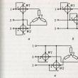
|
New
- Tired MPs want to give Russians a two-hour lunch break. Concepts and categories
- Massage covers Relaxation cape
- Relaxation cover Ergopower ERSC7H Contraindications and benefits of massage cover
- How to pay for utilities directly to the resource supplying organization When we pay directly to utility providers
- Recommendations for finding a job abroad for Russians, Ukrainians, Belarusians
- Forgot the code word belagroprombank How to set up a mobile key belagroprombank
- The habits of rich people: behavior, thinking and interesting facts What makes a person rich ask
- Belagroprombank personal account Fransabank internet banking login
- How to make money on agricultural tourism in Russia How to open an agricultural estate in Belarus
- How much is the labor of a kindergarten teacher in our country and in other countries?


